Ignition Coil Wiring Diagram - Coil Wiring Diagram Vw Beetle Wiring Diagram All Product Congress Product Congress Huevoprint It / A wiring diagram usually gives recommendation very nearly the relative tilt and pact.. Print the cabling diagram off plus use highlighters to be able to trace the signal. It shows the elements of the circuit as streamlined shapes, as well as the power and also signal links in between the tools. Wiring diagram for ignition coil more information find this pin and more on 63 f100 wiring by ben platt. The ecu sends a signal and each module is responsible to power one coil at the right time. The coils which are the basis for ignition coils and alternators have very specific electronic.
Sqm 012 74 vw beetle ignition coil wiring diagram series graphic centrostudimad it. The typical automotive ignition system prior to 1974 consisted of a coil and ballast resistor, with breaker points to interrupt the current flow when a spark was needed. Wellborn variety of mercruiser ignition wiring diagram. Print the wiring diagram off in addition to use highlighters to be able to trace the routine. Hei ignition systems are very dependable and offer great performance on a number of applications.
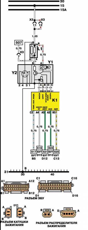
Daewoo Nexia Wiring Diagrams Car Electrical Wiring Diagram from image.jimcdn.com How to test the gm distributor mounted ignition module. The heart of any ignition system is the coil, battery voltage is supplied on the positive side, while the negative side is repeatedly pulsed to ground. Wellborn variety of mercruiser ignition wiring diagram. The aftermarket cdi module must be placed between ecu signal and coil, jumping the stock power modules. March 12, 2019 by larry a. The coils which are the basis for ignition coils and alternators have very specific electronic. A schematic diagram of an electronic ignition system is shown in figure 2.36. The wired differences matt dixon southern illinois university carbondale,.
Ford ignition coil wiring diagram wiring diagram is a simplified enjoyable pictorial representation of an electrical circuitit shows the components of the circuit as simplified shapes and the gift and signal friends amid the devices.
Ford ignition coil wiring diagram wiring diagram is a simplified enjoyable pictorial representation of an electrical circuitit shows the components of the circuit as simplified shapes and the gift and signal friends amid the devices. Cylinder to cylinder variations are valuable. The ecu sends a signal and each module is responsible to power one coil at the right time. 1 trick that we use is to print out the same wiring picture off twice. Print the cabling diagram off plus use highlighters to be able to trace the signal. Sqm 012 74 vw beetle ignition coil wiring diagram series graphic centrostudimad it. One trick that i use is to print exactly the same wiring picture off twice. How to test the gm distributor mounted ignition module. The job of the ballast resistor was to inhibit current to a level that would not overheat the coil. It shows the components of the circuit as simplified shapes, and the capacity and signal friends between the devices. Ignition coil ballast resistor wiring diagram welcome to my internet site this blog post will certainly discuss concerning ignition coil ballast resistor wiring diagram. A wiring diagram is a streamlined standard photographic representation of an electrical circuit. Construction of electronic ignition system:
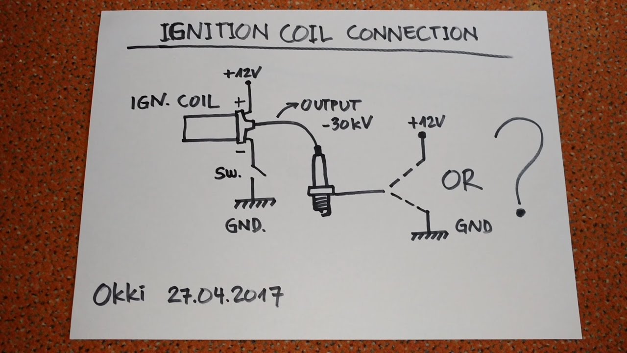
Because the output spark is very much higher voltage (20,000v) than the car battery (12v), it doesn't care if the battery polarity is helping or hindering by a meager 12 to 14 volts in battery potential. It shows the components of the circuit as simplified shapes, and the capacity and signal friends between the devices. This simple system is easy for even the novice mechanic to wire. Cruze has 4 independent ignition coil on plug system, built in one single body, with 4 power modules inside them. Basic ignition system wiring diagram.
2001 Toyota Prius Need Ignition Coil Wiring Diagram First Cylinder 1 Off Harness from www.justanswer.com The purpose of the ignition system is to create a spark that will ignite the fuel air mixture in the cylinder of an engine. The job of the ballast resistor was to inhibit current to a level that would not overheat the coil. The ecu sends a signal and each module is responsible to power one coil at the right time. Sqm 012 74 vw beetle ignition coil wiring diagram series graphic centrostudimad it. This tutorial will help you test the ignition coil, ignition module, and the crankshaft position sensor: Vw coil wiring narrate database beetle ignition 65 bug diagram 69 fusebox and 1600 74 73 ddiagrams plug wire electronic ghia full carb data pair nice 1971 ambassador car engine distributor 72 generator 87 dodge dakota auto along with gm ls1 sultan replacem connector on 2002 ls 430 olds 88 v6 1979 headlight. Ignition coil ballast resistor wiring diagram welcome to my internet site this blog post will certainly discuss concerning ignition coil ballast resistor wiring diagram. Print the cabling diagram off plus use highlighters to be able to trace the signal.
How to test the gm distributor mounted ignition module.
A wiring diagram is a streamlined standard photographic representation of an electrical circuit. One trick that i use is to print exactly the same wiring picture off twice. The faults for bad ignition coils could be misfires on a single or multiple cylinders with possible fault codes being p, p (for cylinder. This simple system is easy for even the novice mechanic to wire. The coil primary winding contains 100 to 150 turns of heavy copper wire. Bank 1 is always on cylinder 1 side. It shows the parts of the circuit as streamlined forms, and the power as well as signal links in between the tools. The typical automotive ignition system prior to 1974 consisted of a coil and ballast resistor, with breaker points to interrupt the current flow when a spark was needed. Each part ought to be set and connected with different parts in specific manner. 12 volt conversion wiring diagram mopar flathead truck forum p15 d24 com and pilot house. Lawn mower briggs and stratton ignition coil wiring diagram. Ford ignition coil wiring diagram wiring diagram is a simplified enjoyable pictorial representation of an electrical circuitit shows the components of the circuit as simplified shapes and the gift and signal friends amid the devices. Is this same as the scion tc?
Variety of chevy 350 ignition coil wiring diagram. It contains both primary and secondary winding circuits. 12 volt conversion wiring diagram mopar flathead truck forum p15 d24 com and pilot house. Because the output spark is very much higher voltage (20,000v) than the car battery (12v), it doesn't care if the battery polarity is helping or hindering by a meager 12 to 14 volts in battery potential. The ignition coil is nothing more that an electrical transformer.
Ignition Coil Circuit Confusion Youtube from i.ytimg.com Hei ignition systems are very dependable and offer great performance on a number of applications. Place ignition switch in the off position. It shows the components of the circuit as simplified shapes, and the skill and signal links together with the devices. Vw coil wiring narrate database beetle ignition 65 bug diagram 69 fusebox and 1600 74 73 ddiagrams plug wire electronic ghia full carb data pair nice 1971 ambassador car engine distributor 72 generator 87 dodge dakota auto along with gm ls1 sultan replacem connector on 2002 ls 430 olds 88 v6 1979 headlight. 4.3 vortec ignition coil wiring diagram. However, this diagram is a simplified variant of this arrangement. 12 volt conversion wiring diagram mopar flathead truck forum p15 d24 com and pilot house. The ignition coil is nothing more that an electrical transformer.
It shows the parts of the circuit as streamlined forms, and the power as well as signal links in between the tools.
When you make use of your finger or the actual circuit along with your eyes, it may be easy to mistrace the circuit. The aftermarket cdi module must be placed between ecu signal and coil, jumping the stock power modules. Cylinder to cylinder variations are valuable. Ford ignition coil wiring diagram wiring diagram is a simplified enjoyable pictorial representation of an electrical circuitit shows the components of the circuit as simplified shapes and the gift and signal friends amid the devices. The purpose of the ignition system is to create a spark that will ignite the fuel air mixture in the cylinder of an engine. The job of the ballast resistor was to inhibit current to a level that would not overheat the coil. 2,3 and 4 wire coil versions are different in control & monitoring strategies. Wellborn variety of mercruiser ignition wiring diagram. Sqm 012 74 vw beetle ignition coil wiring diagram series graphic centrostudimad it. This tutorial will help you test the ignition coil, ignition module, and the crankshaft position sensor: The coil primary winding contains 100 to 150 turns of heavy copper wire. 1 trick that we use is to print out the same wiring picture off twice. The wired differences matt dixon southern illinois university carbondale,.